Membrane keypads, switches and keyboards are a specific type of customized circuit assembly that is designed to open or shut it’s current flowing circuit path. A keypad is made of many layers with each of the layer in the assembly construction has its own role.
But what are the basic principles of designing a membrane keypad circuit and what best practices should you adhere to for ensuring your success?
Read in detail: What is Membrane Keypad?
The Function of Graphical Overlays in Membrane Keypads
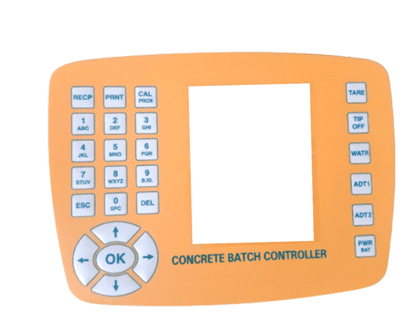
Graphical Overlays and labels are typically utilized for the identification of the front face of the keypad to the user. They are just heavy-duty labels printed on screen or printed on flexible, hard-coated sheets. As they are front face of the keypad, the graphics on the overlay need be high-definition and texts & symbols are distinct.
In the framework of the keypad, graphic overlays constitute the topmost layer. Graphical overlays are made out of a variety of different materials, such as polycarbonate, polyesters and many other materials. Many kinds of adhesives are used to hold the graphic overlays to the surface. Graphic overlays are not equipped with any wires or electrical circuits in any way. They are printed exclusively with polycarbonate or polyester adhesives.
Know More: 7 Designing Factors for Customized Graphic Overlays
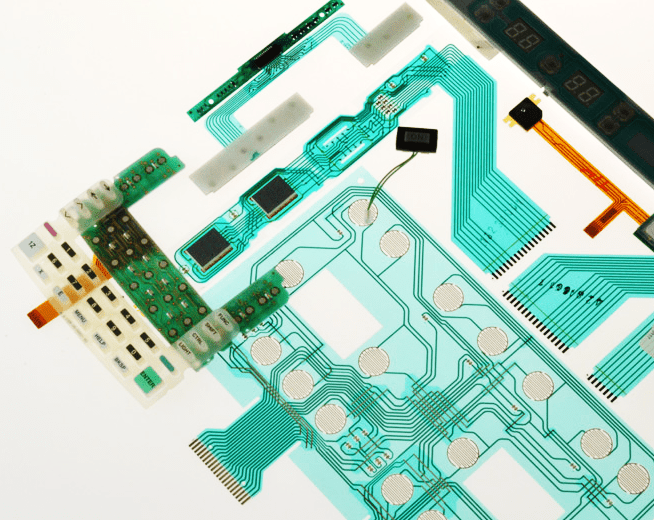
Circuit Layers of Membrane Switches and Their Function
The Membrane switch’s circuit is made out of polyester with silver-colored ink is screen printed as the conductive component on the circuit. A Flexible Polyamide circuit can be employed for better insulation sustenance.
The circuit layer allows surface-mounted components like resistors or LEDs be embedded as they are intended to within the circuit for switching on and off. This layer also allows for keys and various inputs to operate correctly within the layer laminated membrane layers.
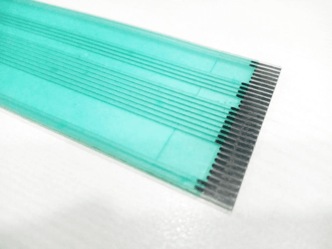
ZIF Connectors
A ZIF connector can be used to connect an electrically powered membrane keypad to the parent PCB. It’s one of the least expensive (and therefore most commonly used) ways of doing so. These connectors often called ZIF tails are made with screened ink or etched copper. These materials are coated in a similar manner to the process used to make the flexible circuits. There are a lot of pins in ZIF connectors. ZIF connector are directly linked to the other switches (or elements) necessary for operation of the circuit. Every pin can be clearly marked on the accompanying schematic diagram.
Read More: Crucial Customizations for Accurate Membrane Keypads
Buffer Areas within keypad profile
Like the name suggests, the buffer area is an essential part of the circuit that must not possess electrical trace. This is, in fact, one of the absolute guidelines for circuit design of membrane keypads. There should be no components in these zones to ensure the proper functioning for the circuit.
Dome switches, LEDs as well as windows, are some of the elements which should not be added to the areas considered as buffer areas. If it is unavoidable to do so, a new layer can be added, but it could add complexity and cost. Sometimes, it’s simpler to move a part just a millimeter.
Also, domes and LEDs are not to be placed near the edges of the switch. There should be enough room for the component to be positioned and attach it properly in the circuit.
Switch Matrix
Switch matrix are comprised of different circuits, which have been laid out in an exact grid of columns and rows. This makes it simple to establish connections wherever circuits are interconnected. This configuration allows for the optimization of the membrane keypad, and also increases the number of button that can be operated using a pin count. A switch matrix can be a great option to decrease both the total number of pins as well as the number of channels required for operation. The fewer pins will allow you to use smaller connectors, which reduce the complexity as well as the total price of the product.
Why membrane keypads must be waterproof
If a circuit with a membrane design has to be certified for outdoor usage, it is recommended that a keypad that is waterproof is typically required. The industry standard recommends that this design be in compliance with IP54 standards, but having higher standards is encouraged.
If the project calls for the use of a waterproof membrane keypad the circuit needs a perimeter buffer area for sealing reasons. Additional space should be included in the circuit design, ranging from 2mm and 6mm all the way to the outside part of the circuit. This should leave enough space for the water-proof seal to be installed without affecting the circuitry.
Summary
As final analysis of this article, membrane keypad circuits provide the flexibility required to meet the demands of various end-user applications. But, if we adhere to best design practices described above we may develop best keypad ever. Making use of a diagram, using a matrix layout for circuits and paying particular attention to waterproofing and knowing buffer areas are all essential to ensure that the final product meets all objectives of a membrane keypad project. If you’d like more details about the top techniques for the design of membrane switch circuits contact Linepro today.